
TECHNICAL REFERENCE DRAFT · Methodology v0.4 · 9 October 2026 · Not an adopted agency rule
Treatment Train Calculation Methodology
Start with the figures. Open each section for the complete engineering method, calculations, assumptions and source record.
Treatment Train Calculation Methodology
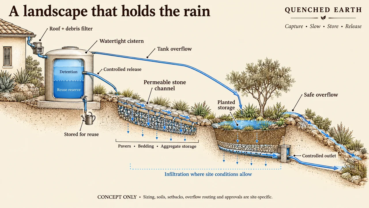
Concept illustration · not to scale · not proof of performance
One system. Three different questions.
Full method, calculations, assumptions and sources
Quenched Earth Engineering • Technical reference draft • Version 0.4 • 9 October 2026
This is a technical reference draft for engineering and agency review. It explains a calculation framework; it does not establish a project approval, a new adopted regulatory method or a completed hydraulic model.
Purpose and method boundaries
The method connects runoff reduction to the development footprint while keeping three calculations separate: the physical movement of water; pollutant-control performance; and hydromodification management performance. A landscape feature receives a defined role and evidence appropriate to that role.
Published WQE and BMP Design Manual methods are identified by edition and section, with their eligibility conditions. This revision documents a guidance gap identified in the reviewed provisions and Stuart Kuhn, P.E.’s proposed engineering interpretation for downstream equivalent-area sizing. The interpretation and the separate credit ledger are disclosed for agency review; neither establishes an adopted serial-HMP method or automatic compliance.
- Physical model: surveyed drainage areas, connected flow paths, storage, infiltration, reuse, outlets, overflow and bypass. Units include square feet, cubic feet and cubic feet per second.
- Water quality: design capture, provided capture and pollutant-specific removal efficacy under the accepted method. Equivalent impervious area is a method-specific reporting quantity.
- HMP: qualifying source-specific sizing-factor calculations or project-specific continuous simulation. An HMP managed-area claim is conditional on the applicable criteria and local acceptance.
How a report should use this reference
A project report may cite a fixed version and named section of this reference after review. The report must retain its own drainage exhibits, source editions, inputs, calculations, model files, results and professional conclusions. A changing webpage must not become the only record supporting a signed report.
Navigation
The sections below define quantities, establish the physical network, describe stage balances, separate pollutant and HMP accounting, work through the area-ledger example, map the reviewed workbook and identify the evidence required for a project decision.
Quantities and units
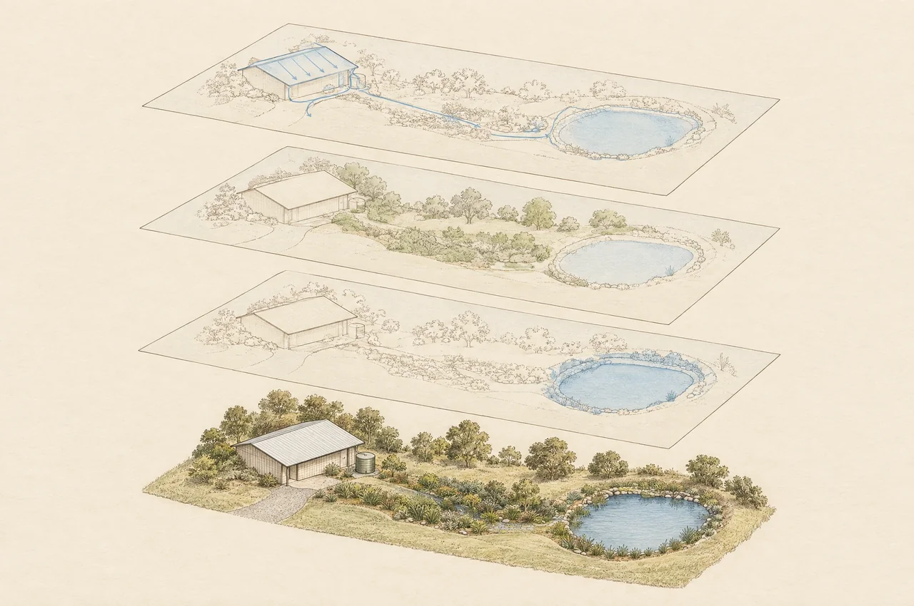
Concept illustration · not to scale · not proof of performance
Keep the three area quantities apart.
Full method, calculations, assumptions and sources
Physical area and equivalent area
Physical tributary area is the mapped land surface contributing runoff to a node. It remains part of the drainage network even when upstream treatment reduces its pollutant-control obligation. Directly connected impervious area, or DCIA, is a physical-connectivity classification whose eligible extent must be established for the selected method.
Equivalent area is a method-specific reporting or sizing quantity. Keep four distinct fields: WQ equivalent area, earned HMP managed DCIA, remaining credit obligation, and the proposed downstream HMP equivalent-area surrogate. None changes the surveyed catchment or removes actual outlet, overflow or bypass flow from the physical system.
Required unit conventions
- Area A: square feet for project entries; divide by 43,560 to obtain acres when a source equation requires acres.
- Rainfall depth P and infiltration rate f: inches and inches per hour unless explicitly converted. Divide depth by 12 to obtain feet.
- Storage S and water volumes V: cubic feet. One cubic foot is approximately 7.48052 US gallons.
- Flow q: cubic feet per second. Use seconds for an integral or time-step calculation with that unit.
- WQE provided capture Ccap: a dimensionless method-specific quantity, not universally bounded by one; qualifying biofiltration can use up to 1.5. Pollutant removal E is a dimensionless efficiency; use the prescribed convention and evidence. Ccap is not the Rational Method runoff coefficient.
- HMP sizing factor F: retain the source’s dimensional definition. An area/area factor is dimensionless; do not apply it to a volume without the source’s cross-section or separate conversion.
A dimensional check for volume methods
V = (P / 12) × A × Cr
In this dimensional relationship, P is inches, A is square feet and Cr is a dimensionless runoff factor from the applicable volume method; V is cubic feet. This is not a universal substitute for the governing DCV equation, continuous runoff model or event hydrograph. Never combine rainfall inches directly with a cubic-foot residual when back-calculating an effective factor.
Do not merge source-specific runoff factors
The County September 2020 HMP sizing basis uses physical tributary area and the independent HMP runoff factors in Table G.2-1. The WQE 2018 Example 3-4 uses eligible tributary DCIA directly. WQ equivalent area and a WQ runoff factor do not silently substitute for either basis. [County of San Diego BMP Design Manual Appendix G September 2020] [Water Quality Equivalency Guidance Document May 2018]
Physical drainage network and inputs
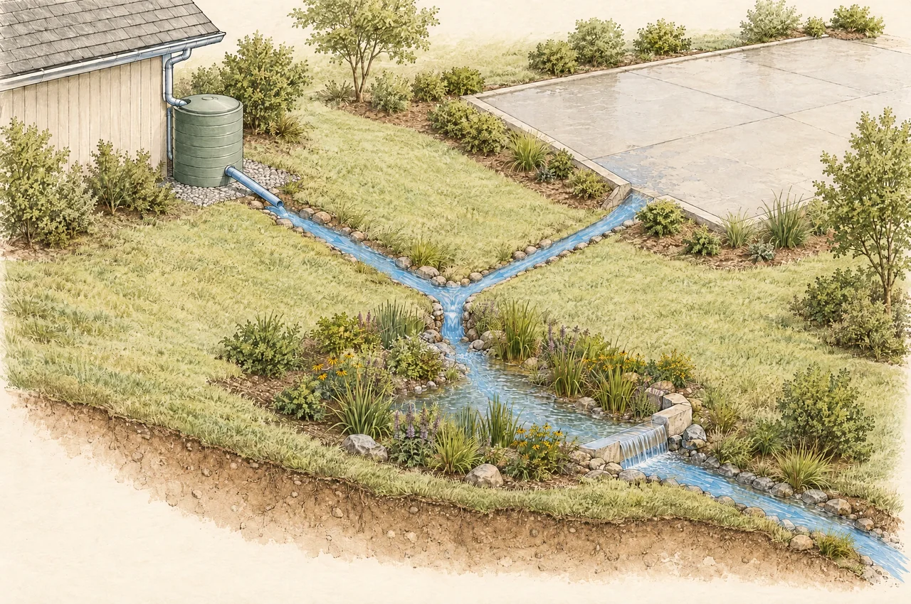
Concept illustration · not to scale · not proof of performance
Trace every path and every joining area.
Roof → cistern → channel → planted storage → downstream
New pavement → its defined joining node
Overflow and bypass → their separately defined destinations
Full method, calculations, assumptions and sources
Represent the development as mapped source areas connected to explicit nodes. A conceptual roof → cistern → stone channel → planted storage train may have several additional paths: tank overflow to the basin, pavement joining downstream, channel bypass, an underdrain and final overflow. Document each connection and its destination.
Minimum input record
- Drainage map: unique area identifiers, measured physical areas, surface type, slopes, land-use condition, eligible DCIA and points where new runoff enters.
- Rainfall and runoff: source and period of record, temporal resolution, applicable design events or continuous series, predevelopment and proposed assumptions, loss parameters and model version.
- Storage: stage–storage relationship, dead storage, reuse reserve, available detention, initial state, overflow elevation and any media or aggregate void storage.
- Outlets: stage–discharge relationship, invert and orifice geometry, discharge coefficient, tailwater assumptions, clogging sensitivity and receiving node.
- Losses and use: geotechnically supported design infiltration, wetted area, restrictions, actual demand schedule, withdrawal destination, seasonal ET assumptions and recovery between storms.
- Evidence: survey, field tests, geotechnical recommendations, source sections, maintenance requirements and documented jurisdictional method acceptance.
Stage mass balance and routing
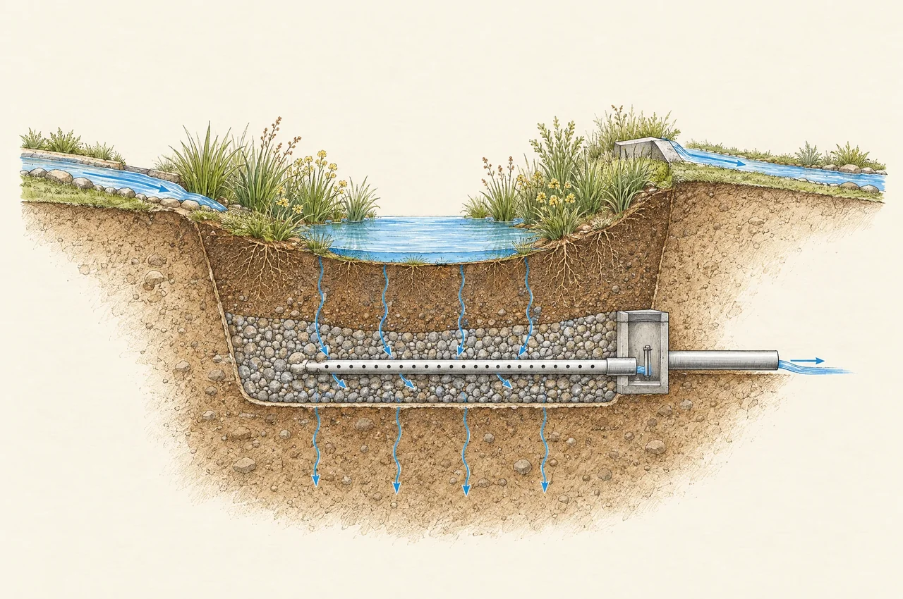
Concept illustration · not to scale · not proof of performance
Account for water, stage by stage.
S_end = S_start + V_in + V_precip − V_inf − V_use − V_ET − V_out − V_over
Full method, calculations, assumptions and sources
Define a control volume for each stage
Use the actual storage boundary of the cistern, channel or basin. A time step begins with stored water, receives admitted inflow and direct precipitation, then accounts for losses and discharge. The proposed balance below is a conservation statement, not a calibrated runoff or outlet model.
S_end = S_start + V_in + V_precip − V_inf − V_use − V_ET − V_out − V_over
All terms are cubic feet over the same time step, including V_precip; rainfall depth alone cannot enter this sum. V_in includes only water entering the control volume; V_precip is direct precipitation on it where applicable. V_inf is infiltration leaving that control volume, V_use is an actual withdrawal, V_ET is evapotranspiration, V_out is controlled discharge or underdrain flow, and V_over is overflow. Identify their receiving compartments or destinations. Terms must be mutually exclusive actual fluxes: for example, do not count irrigation withdrawal as V_use and again as V_ET from the same control volume.
V_flow = integral of q(t) dt
If flow is in cubic feet per second, integrate with time in seconds. The time step, numerical solution and stage–storage–discharge relationships must resolve the changing head and inflow; simply multiplying a nominal outlet rate by a storm duration does not establish routing.
Bypass and downstream continuity
Water diverted before a stage’s storage is bypass and does not enter that storage balance. Route it separately to its actual destination. At the next node, combine routed controlled release, overflow, relevant bypass and runoff from newly connected physical areas. Do not send bypass to both the next node and the terminal outlet unless the flow is explicitly split.
Retention and detention have different consequences
Water temporarily stored and later released remains in downstream accounting. A reserved tank volume is not a demonstrated reuse loss; actual demand must withdraw it and create available capacity. Infiltration out of a media layer is not necessarily loss from the whole site if an underdrain or shallow return path conveys it downstream.
Conservation checks
Require storage to remain between zero and physical capacity. Reconcile inflow, initial storage, final storage, each loss and every discharge. Specify a defensible numerical tolerance and report the balance residual. At the overall system boundary, internal transfers cancel; they must not be counted again as new water or repeated retention. A closed balance supports an audit but does not itself demonstrate HMP flow-duration compliance.
Stage design and performance assumptions
Concept illustration · not to scale · not proof of performance
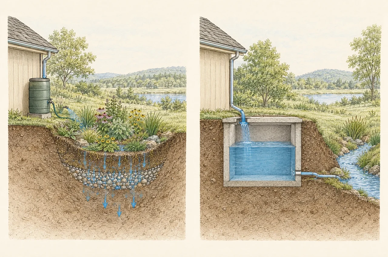
Retention changes volume. Detention changes timing.
Full method, calculations, assumptions and sources
Cistern
Separate detention capacity from dead storage and reuse reserve. Evaluate the available starting volume, actual demand, release control, overflow and backwater. A fixed irrigation demand during a wet period is not automatically achievable. Do not credit the same volume as both permanent reuse retention and controlled release.
County Appendix G §G.2.5 sizing factors assume controlled release rather than retention. They do not account for combined storage or retention in downstream BMPs, and the required low-flow outlet can conflict with other system elements. The source recommends project-specific continuous simulation when optimizing cistern systems that include use, infiltration or biofiltration. [County of San Diego BMP Design Manual Appendix G September 2020]
Engineered stone channel
Identify whether the feature is conveyance, a permeable pavement section, an infiltration facility, treatment media or some combination. Concentrated flow in a stone channel does not automatically meet sheet-flow dispersion criteria. Document velocity, erosion resistance, usable void storage, subgrade infiltration, bypass and the effects of clogging.
Tree well or planted basin
Use the actual section: surface ponding, soil media, aggregate, liner, underdrain, outlet and native soil. A label such as tree well does not establish eligibility for a prescriptive no-underdrain method. Disclose when a downstream sizing input uses the proposed equivalent-area interpretation in the serial-ledger section; that surrogate does not represent the actual routed inflow hydrograph.
Outlet and overflow
The ordinary outlet must be compatible with the selected HMP or treatment method and the receiving facility. Check available head, downstream tailwater, debris, clogging and maintenance access. Provide an exceedance route for full storage, wet soils and events beyond the treatment design condition. A water-quality result does not demonstrate flood safety.
Geotechnical and operational limits
Evaluate slope stability, fills, restrictive soil layers, shallow groundwater, contamination, foundations, utilities and onsite wastewater systems. Define long-term infiltration and sediment-management assumptions. Test sensitivity to reduced infiltration, diminished storage, unavailable reuse demand and blocked controls. Changes to those assumptions can invalidate both modeled performance and claimed credit.
Water quality and treatment train efficacy
Concept illustration · not to scale · not proof of performance
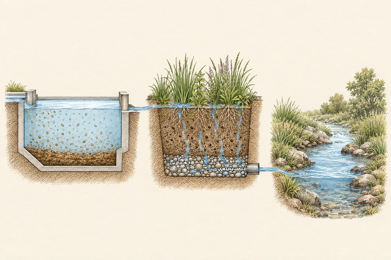
Treat the remaining pollutant burden.
Full method, calculations, assumptions and sources
Apply the accepted pollutant-control method
Define the applicable water-quality target, design capture volume or water-quality flow, pollutant suite and baseline. Then document provided capture and removal efficiency for each eligible element. The WQE guidance and Worksheet A.4 provide a published treatment-train framework; local use still depends on the governing program and project eligibility. [Water Quality Equivalency Guidance Document May 2018]
Keep capture and removal separate
Provided capture is a method-specific normalized measure of capture; removal efficiency describes the applicable pollutant-removal convention. WQE biofiltration can use provided capture up to 1.5 with the prescribed 0.666 removal convention, so it is not always a literal fraction of runoff between zero and one. Upstream retention and treatment change what reaches the next element. Source evidence must support downstream capture under the actual release, overflow and bypass pattern. Nominal tank capacity does not supply that capture fraction.
The source’s common-tributary-area worksheet combines incremental pollutant efficacy against the remaining untreated fraction. Standalone removal percentages should not be added. Mixed retention, volume-based and flow-based elements require additional capture considerations; Appendix B.2.1 specifically addresses reductions in upstream pollutant concentration. [Water Quality Equivalency Guidance Document May 2018]
Source locations for review
Use printed pp. 30–39 for treatment-train concepts, §2.3.1.3.2.5 on p. 38 for provided capture, Example 2-8 on pp. 43–45, Worksheet A.4 on p. A-7 and Appendix B.2.1 on p. B-28. In the verified file these correspond to PDF pp. 62–71, 70, 75–77, 167 and 198 respectively.
The source has equation cross-reference and presentation inconsistencies noted during review. This draft therefore does not reproduce a generalized source equation as a new approved rule. Use the reviewed worksheet implementation, documented inputs and engineering check; preserve the exact source edition.
Independent output
Report pollutant-specific efficacy and its assumptions separately from storage recovery, peak flow and HMP performance. Pollutant efficacy B and its residual fraction alone do not calculate alternative-compliance earned volume or tradable credit; those require the applicable baseline, land-use factors, capture-volume accounting and program rules. A fraction bounded at 1.00 does not establish water conservation, eliminate bypass or prove compliance with a flow-duration standard. Proposed serial-area bookkeeping must not be used to manufacture a capture fraction.
Published HMP partial area method
Concept illustration · not to scale · not proof of performance
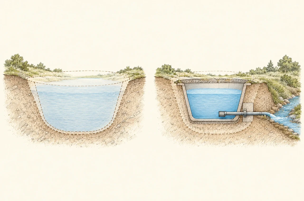
A size ratio still needs an eligibility gate.
Full method, calculations, assumptions and sources
WQE 2018 method and example
WQE §3.7.1.1, printed pp. 71–73, permits partial earned HMP DCIA from an undersized qualifying BMP using applicable Appendix G.2 sizing factors, including qualifying detention configurations. Its configuration and outlet conditions remain controlling. Determine required size using the eligible source basis and selected standard configuration, then compare provided and required size in the same units. [Water Quality Equivalency Guidance Document May 2018]
Required BMP size = applicable sizing basis × documented sizing factor
Sizing-only managed DCIA = eligible tributary DCIA × min(1, provided size / required size)
This ratio expresses the source’s partial-area concept. The min(1, ratio) cap is a conservative implementation consistent with unique eligible DCIA and WQE’s up-to-100-percent benefit limit, not a verbatim §3.7.1.1 equation. Required size must be positive. The ratio is not supported credit until source applicability, configuration, outlet and local acceptance are demonstrated. A zero or missing denominator is an invalid input, not zero credit or full compliance.
Example 3-4 uses 30 acres of tributary DCIA and an area sizing factor of 0.050. Required BMP area is 1.5 acres; 0.3 acre provided yields a ratio of 0.20 and manages 6 acres. The outlet is sized for the allowable flow associated with the 6 credited acres. The factor 0.050 belongs to that example, not every project.
Eligibility conditions remain part of the result
- Table 3-2 limits the sizing-factor method to the 0.1Q2 low-flow-threshold category; do not extend it to other thresholds without a supported method.
- Table 3-3 requires the applicable standard cross-section and minimum infiltration, a conforming outlet orifice, no new diversion at the HMP compliance point, and no additional outlet below the standard overflow.
- Use the applicable manual’s geometry, infiltration, factor, outlet and source conditions together. Do not interpolate or mix configurations unless the accepted method allows it.
- In the reviewed WQE §3.7.1.1 and County Appendix G provisions, no explicit translation was identified from earned partial HMP DCIA to a natural-equivalent runoff factor for downstream serial sizing. This is a bounded finding about the reviewed provisions, not a claim that no treatment-train study or applicable guidance exists elsewhere.
Do not combine the County and WQE area bases
County Appendix G September 2020 calculates size from the sum of physical tributary areas multiplied by their HMP Table G.2-1 runoff factors and the selected sizing factor. Its low-flow Q2 basis uses physical tributary acres and unit Q2. WQE Example 3-4 uses DCIA directly. Select and document the governing basis; the County source is not automatically Temecula authority. [County of San Diego BMP Design Manual Appendix G September 2020]
BMP menu and sizing-factor crosswalk
Concept illustration · not to scale · not proof of performance
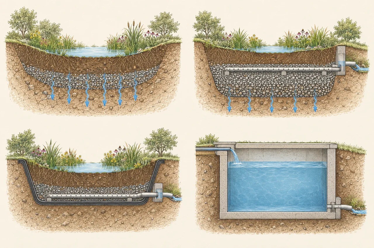
Match the section before choosing a factor.
INF-3’s 4:1 total-drainage-area:pavement-area recommendation is a pollutant-control loading caution, not an HMP-credit ratio. Open detention remains a conditional applicability interpretation. See the complete crosswalk below.
Full method, calculations, assumptions and sources
The Appendix E BMP menu is broader than Appendix G’s four factor configurations. Select the performance method by the actual section and function, rather than by a landscape label. This crosswalk records the reviewed September 2020 sources; it does not supply missing factors or extend WQE partial-credit eligibility.
| BMP / configuration | Source / route | Method / evidence | Limitation |
|---|---|---|---|
| Full infiltration | G.2.2; Table G.2-3 | Area factor; specified ponding and infiltration; no underdrain | Match the standard configuration; an INF label alone is insufficient |
| Partial-retention biofiltration | G.2.3; Table G.2-4 | Area factor; media, ponding, gravel, raised controlled underdrain; unlined | Preserve the full section and outlet assumptions |
| Lined biofiltration | G.2.4; Table G.2-5 | Area factor; media, ponding, gravel and controlled underdrain; lined | A gravel-only section is not this configuration |
| Cistern / controlled detention | G.2.5; Table G.2-6 | Volume factor; controlled release, specified overflow/head | Retention is uncredited; this does not make actual infiltration physically negligible |
| Site design: SD-A–SD-F | Appendix E menu; SD-A/SD-B; Section 5.2.3 | Trees, dispersion, green roofs, pavement, rain barrels, amended soil | Qualifying tree/dispersion routes are separate; do not assign a generic G.2 factor |
| HU-1; INF-1/2/4; PR-1; BF-1/2/3 | Appendix E fact sheets; selected G.2 configuration | Harvest/use, basins, bioretention, dry wells, partial-retention and biofiltration variants | Check the individual fact sheet and configuration; category membership is not factor approval |
| INF-3 pavement receiving run-on | INF-3, E-92–E-93 | Iterative flow-control design: aggregate depth/area, infiltration and/or detention, outlets | No dedicated named G.2 pavement factor; downstream controls may address remaining needs |
| FT-1–FT-5, including extended detention | Appendix E menu; compare G.2 | Swales, media/sand filters, dry extended detention, proprietary flow-through treatment | No separately named extended-detention G.2 factor; pollutant treatment does not itself establish HMP credit |
| Serial or nonstandard combination | WQE §§3.7.1.1, 3.7.1.3; serial-ledger section | Separate earned partial credit, proposed sizing surrogate and physical routing | No automatic factor borrowing, serial-credit accumulation or natural-hydrograph equivalence |
Permeable pavement: loading ratio, own surface and run-on
INF-3 E-87 recommends total drainage area, including pavement, divided by pavement area not exceed 4:1 for pollutant control; clogging risk drives the caution. It is not an HMP-credit ratio. E-94’s maintenance discussion describes a smaller surrounding-area ratio; disclose and resolve that difference rather than treating 4:1 as universal approval.
Table G.2-1 assigns runoff factors to surfaces. Engineering application: apply the pavement’s factor to its own eligible surface area; do not automatically apply it to roof or pavement run-on. Any reduction of upstream runoff needs its own stated basis. This is distinct from Stuart Kuhn’s proposed managed-share interpretation in the serial-ledger section.
For an aggregate-only project section, record footprint, usable reservoir depth, effective void fraction, infiltration, liner, underdrain and outlet elevations. Storage arithmetic uses only physically present, hydraulically available voids. Do not borrow a biofiltration factor while omitting its media or surface ponding. “Aggregate-only” describes the selected project section; it does not assert that every INF-3 design has identical layers.
Open detention basin: applicability judgment
G.2.5 defines cistern functionally as controlled detention and permits differing vessel heights with conforming volume/outlet design. No separately named extended-detention factor appears in the reviewed G.2 tables. Engineering interpretation: an open basin is a possible candidate only after documenting compatible stage–storage, outlet head/discharge, overflow and required volume. The definition alone does not approve arbitrary sloped-sided geometry or establish identical performance.
A basin applicability record should show the actual stage–storage curve, usable volume, operating head, lower control, overflow elevation and any losses or bypass. Uncredited infiltration remains a physical process to describe. These are disclosure requirements for the interpretation, not new modeling results or a commitment to perform modeling. The selected 0.10 managed-share factor remains Stuart Kuhn, P.E.’s interpretation, not County/WQE adoption.
Reviewer disposition: identify which row governs each component, the source/configuration evidence, any departure and its engineering rationale, the proposed credit or sizing quantity, and the unresolved acceptance question. Preserve the earlier eligibility gates. A gap in a tabulated factor is not proof that the BMP lacks an HMP design route.
Crosswalk sources: County Appendix E September 2020. County Appendix G September 2020.
Serial systems and the planning ledger
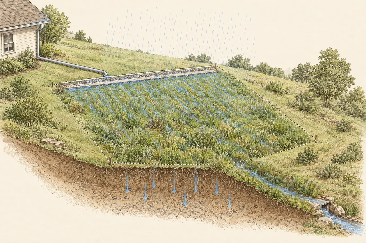
Concept illustration · not to scale · not proof of performance
An upstream benefit is not a deleted hydrograph.
Its credit must have its own applicable method and evidence. Avoid overlapping credit.
Route actual releases and bypass. A chain alone does not establish additional credit.
Full method, calculations, assumptions and sources
Published simulation route and scope of this revision
WQE §3.7.1.3 describes a project-specific continuous flow-duration analysis route. County Appendix G §G.2.5 recommends continuous simulation when optimizing combined cistern systems. This revision documents engineering judgment and the reviewed guidance gap without new modeling, calibration or validation. It does not promise a later modeling exercise. The proposed sizing interpretation remains subject to jurisdictional review. [Water Quality Equivalency Guidance Document May 2018] [County of San Diego BMP Design Manual Appendix G September 2020]
County §G.1 p. G-17 describes serial SWMM LID representation through separate LID subcatchments with upstream run-on. Mixed LID controls placed within one parent subcatchment do not by themselves represent a treatment sequence. Model topology must match actual connections; selecting a model name does not establish correct routing.
A separate credit-obligation ledger
The ledger communicates the physical areas associated with unresolved management obligations. It is distinct from the proposed equivalent-area sizing surrogate below. Any earned-credit entry requires an independently applicable method and evidence; local acceptance remains a separate condition. Never substitute pollutant efficacy or WQ equivalent area for an HMP managed fraction.
Nominal unresolved area = upstream unresolved area + newly added eligible area − independently supported incremental credit
Maintain unique area identifiers, criterion, source method and credited extent. Incremental credit must already be accepted net of earlier credit for overlapping catchments; a nonnegative total alone does not prevent double counting. A negative balance indicates over-allocation or inconsistent inputs and must be flagged, rather than silently hidden by a zero floor.
The 1000 square foot roof example
- Physical roof catchment: 1,000 square feet.
- Hypothetical accepted roof-area credit: 500 square feet under a separately established method. This example does not validate how that credit is earned.
- Roof obligation remaining in the planning ledger: 1,000 − 500 = 500 square feet.
- New pavement joining downstream: 500 square feet. Nominal downstream ledger obligation: 500 + 500 = 1,000 square feet.
- Physical tributary catchment at the downstream facility remains 1,500 square feet: the original 1,000-square-foot roof plus 500 square feet of pavement.
The downstream inflow must include actual cistern outlet discharge and overflow, relevant bypass and pavement runoff. Removing 500 square feet from a ledger does not remove the corresponding roof hydrograph. If the upstream credit depends on downstream treatment, it cannot also be treated as independently completed upstream credit.
Serial credit must not be obtained by automatically multiplying partial-HMP fractions or adding overlapping stage credits. The downstream sizing surrogate below is a disclosed engineering interpretation, not a replacement physical catchment and not a rule for awarding additional earned credit.
Guidance gap identified in reviewed provisions
The reviewed provisions establish partial HMP management credit and source-specific sizing factors, but do not explicitly state how that credited extent becomes a natural-equivalent runoff factor for the next BMP in a series. Earning partial managed DCIA and assigning a downstream runoff factor therefore remain separate steps. The gap concerns that translation, not whether detention can earn qualifying partial benefit.
The underlying Brown and Caldwell (2012) sizing-factor study, §§1.4.2–1.4.3, pp. 1-14–1-16, did model specific cistern-to-bioretention and bioretention-to-vault configurations. Those configurations do not establish a general serial-credit conversion for an arbitrary train. County Appendix G §G.2.5, pp. G-48–G-49, explains that the published cistern factors do not account for combined storage or retention and recommends simulation for system optimization. WQE Appendix C.1’s Sutherland effective-impervious-area discussion, printed pp. C-4–C-6, is not validation of the proposed serial conversion.
Proposed engineering interpretation for downstream sizing
Stuart Kuhn, P.E. proposes an engineer-selected weighted runoff factor for the downstream HMP sizing input. The managed share is represented by a selected landscape/natural-equivalent factor of 0.10, and the remaining share retains the applicable HMP impervious factor, taken as 1.0 in this example. The assignment of 0.10 to an already-managed share is the engineering interpretation; it is not an adopted County or WQE conversion rule.
C_equiv = f_HMPmanaged × 0.10 + (1 − f_HMPmanaged) × C_HMPimpervious
A_equiv,upstream = A_physical,upstream × C_equiv
Here f_HMPmanaged is the independently established managed fraction for the upstream source, between 0 and 1; it is not a water-quality removal fraction. C_HMPimpervious must be the applicable HMP factor rather than an imported WQ factor. A_equiv is a weighted-area sizing surrogate in square feet. Newly joining areas are weighted under the same documented HMP basis before combining them.
Meeting an HMP flow-duration criterion does not demonstrate a hydrograph identical to the natural condition. The selected 0.10 runoff factor is also distinct from the 0.1Q2 low-flow threshold: one is a dimensionless landscape-factor assumption; the other is a flow threshold defined relative to Q2. Neither establishes the other.
The 2,000 square foot roof and 8,000 square foot pavement example
- Physical upstream roof: 2,000 square feet. Assumed independently supported HMP managed fraction: 50%, corresponding to 1,000 square feet of earned managed DCIA. The example assumes that upstream qualification; it does not award it.
- Proposed weighted factor: C_equiv = 0.50 × 0.10 + 0.50 × 1.0 = 0.55. Roof downstream sizing surrogate: 2,000 × 0.55 = 1,100 square feet.
- New impervious pavement joining downstream: 8,000 square feet at HMP factor 1.0. Combined proposed downstream sizing surrogate: 1,100 + 8,000 = 9,100 square feet.
- Credit ledger: 10,000 − 1,000 = 9,000 square feet of remaining management obligation. The 9,100-square-foot sizing surrogate is not this credit balance and does not create additional earned credit.
- Physical tributary catchment: 2,000 + 8,000 = 10,000 square feet. Actual roof releases, overflow and bypass still join the downstream flow according to their physical connections.
Partial dispersion: proposed area-ratio example
The County SD-B full significant-site-design (SSD) pathway uses impervious area divided by qualifying receiving pervious area of 1:1 or less, with all other conditions satisfied. More receiving landscape is compatible with that ratio; an overloaded receiving area fails this full-SSD pathway. The following partial-area allocation is Stuart Kuhn, P.E.’s proposed engineering assumption for review, not a prescribed Appendix I equation or a demonstrated WQE proportional-dispersion rule.
Assume a 2,000-square-foot roof drains to 1,000 square feet of qualifying receiving landscape. Assume every non-area SD-B condition is satisfied, including at least 11 inches of compliant amended soil, at least 10 feet of sheet-flow travel, slope less than 5%, suitable inlets/energy dissipation, vegetation and maintained drainage. These are illustrative assumptions, not verified site findings. The actual impervious:receiving-area ratio is 2:1, so full SSD qualification is not established.
Proposed f_dispersion = min(1, qualifying receiving area / required receiving area at 1:1)
For positive roof area, the required receiving area at 1:1 equals the roof area. Here f_dispersion = min(1, 1,000 / 2,000) = 0.50. The proposed roof managed-area allocation is 2,000 × 0.50 = 1,000 square feet. This is a proposed credit assumption, not independently earned or accepted HMP credit. Negative areas or a zero required-area denominator are invalid inputs.
Applying the separate proposed managed-share factor interpretation gives the roof-only downstream sizing surrogate: 2,000 × (0.50 × 0.10 + 0.50 × 1.0) = 1,100 square feet. Both the partial dispersion allocation and the use of 0.10 for its managed share require explicit engineering disclosure and agency consideration.
Keep the receiving landscape’s own 1,000-square-foot physical area and rainfall/runoff contribution separate. It is not removed by assigning a proposed managed fraction to the roof. If both areas contribute to the same downstream node and the applicable landscape HMP factor is 0.10, its own weighted contribution is 100 square feet; the combined sizing surrogate is then 1,100 + 100 = 1,200 square feet. The physical catchment remains 3,000 square feet. Count each physical surface once; do not count the receiving landscape again as an extra roof-credit area or as demonstrated retained volume.
The linear area-ratio allocation has not been shown here to produce a linear hydrologic response. WQE’s annual-retention approach is a separate alternative requiring retained-runoff evidence and the applicable soil-specific target and cutoff; a receiving-area ratio alone does not provide those inputs. This example supplies no retention measurement, modeled performance or automatic compliance conclusion, and does not change workbook formulas.
Source boundary: County BMP Design Manual, September 2020, SD-B pp. E-17–E-18 establishes the full-path criteria. The partial allocation and downstream arithmetic above are proposed engineering interpretation. The reviewed WQE source remains controlling for any separately claimed annual-retention benefit.
Assumptions and disclosure for agency review
Identify the independently supported upstream managed extent; source edition and applicable HMP factor; selected 0.10 assumption and its engineering basis; connected drainage areas; downstream configuration; and all relevant release, overflow and bypass paths. Disclose storage recovery, reuse availability and timing assumptions, and prevent overlapping credit. Retain the full physical area for drainage continuity and separate flood-safety evaluation.
Present the interpretation expressly as Stuart Kuhn, P.E.’s proposed engineering judgment for agency consideration. No new modeling was performed for this revision, and the weighted factor has not been demonstrated here to reproduce flow duration, peak discharge, volume, timing or a natural-condition hydrograph. Agency acceptance and project compliance are not established by this document or its arithmetic. These limitations remain part of the interpretation wherever it is cited.
Workbook calculation map

Concept illustration · not to scale · not proof of performance
Use the workbook as a traceable calculation record.
Full method, calculations, assumptions and sources
This map describes Quenched Earth - Stormwater Treatment and HMP Review v0.4.xlsx. The notes-only v0.4 revision preserves the formula, input and output locations mapped below. Methodology!B182:B189 records the equivalent-area interpretation; B192:B211 adds the BMP crosswalk. Both are explanatory text, not new calculations. Preserve this workbook version with the report.
| Calculation | Verified workbook location | Interpretation |
|---|---|---|
| Project inputs | Project inputs!E:N; rows 6–60, 62–76, 80–119, 128–135 | Ten DMA columns. Geometry/network: 6–60; HMP criteria: 62–76; WQE stages: 80–119; physical/weighted HMP basis: 128–132; revision/date: 134–135. |
| HMP outputs | HMP partial credit!E:N; rows 11–17, 20, 32–35 | Required/provided size: 11/12; raw ratio: 13; capped sizing-only area: 14; eligibility gate: 15; supported credit: 16; unmet area: 17; decision: 20; source and physical-area basis: 32–35. |
| WQE outputs | WQE train; DMA block header at row 7 + 9i, i = 0–9; next seven rows are pollutants | D/E/F: stage 1 capture/removal/incremental efficacy; G/H/I: stage 2; J/K/L: stage 3; M: cumulative B; N: residual. Header C: status; header O: selected tributary DCV. No full ACP earned-volume result. |
| Project summary | Introduction!D9:K19 | Summary of DMA calculations. Status and eligibility limitations remain controlling; summary values are not hydraulic-routing results. |
| Planning example | Review example!E5:E7, E9:E10, E12, E14 | Hypothetical inputs, roof residual, nominal downstream obligation, physical catchment and hypothesis/invalid-input guard. Separate from project credit. |
| Legacy calculations | Step 1. DCV; Step 2. Dispersion Areas; Step 3. Tree Wells | Baseline DCV, dispersion and tree-well calculations remain distinct. Tree-well row 38 reports capture and row 54 validates geometry. These are not a serial time-series model. |
| Audit trail | Methodology (notes: B182:B189; B192:B211); Sources and changes; Validation | Workbook method notes, source/revision record and validation. Preserve these with the issued workbook and project report. |
Workbook scope
The workbook organizes inputs, sizing checks, pollutant efficacy and a planning example. It does not perform continuous rainfall-runoff or hydraulic routing. The new engineering interpretation is explanatory methodology text only; it is not an implemented C_equiv formula, a new default or a verified serial-performance output.
Gated output
Sizing-only ratios can be displayed while eligibility remains unresolved. Supported credit requires source, geometry, outlet and local-acceptance checks. Existing eligibility gates remain controlling. Recording an engineer-selected downstream surrogate does not convert a serial or controlled-dosing result into accepted HMP credit.
Versioned project evidence
Record filename, version, calculation engine, recalculation date and evidence for manual entries. Preserve formulas and test results. Native Excel execution was not tested for this draft; verify native recalculation before project reliance. Before public webpage publication, check audience access to every reference and preserve the downloaded source editions.
Workbook v0.4 is a separate calculation record. Project-specific workbooks and their data are not published here.
Verification reporting and source record
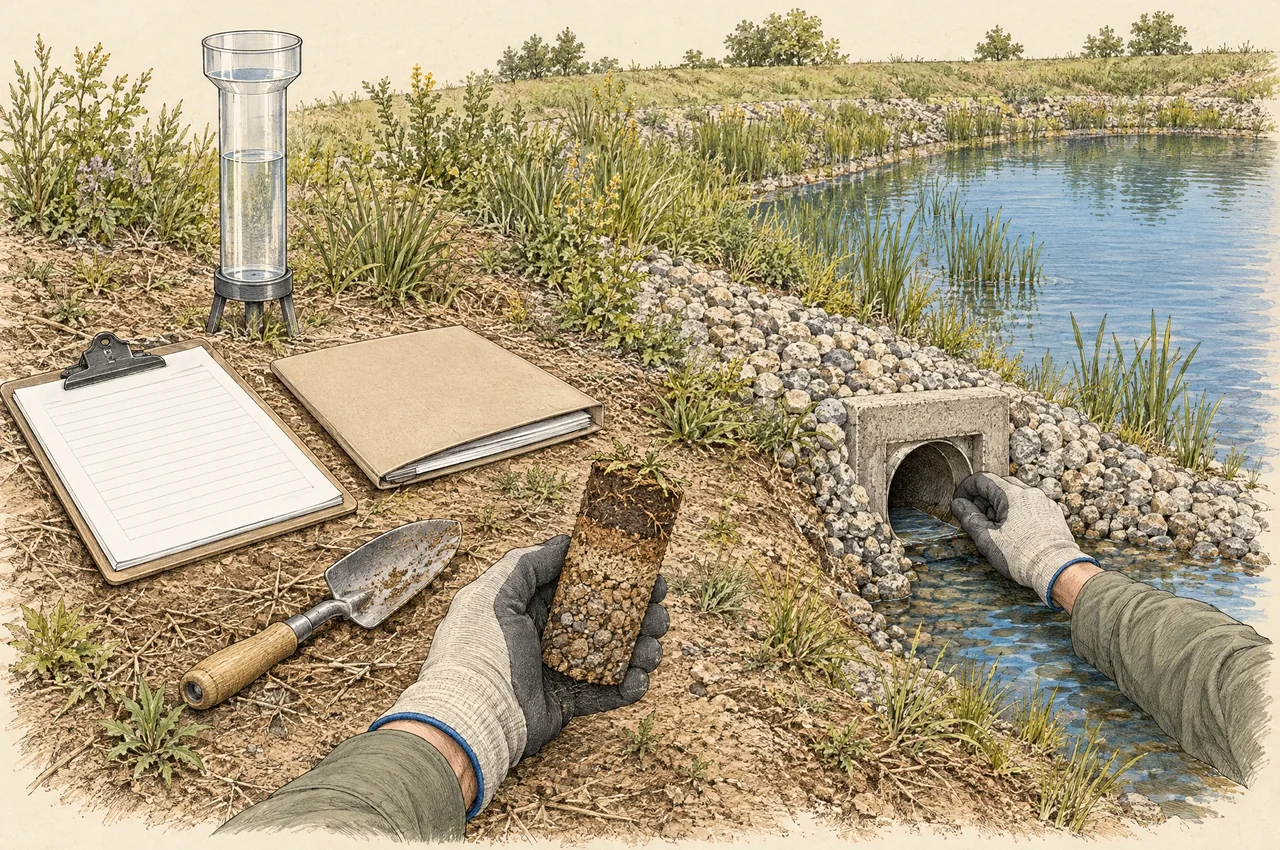
Concept illustration · not to scale · not proof of performance
Show the evidence behind every claimed result.
Full method, calculations, assumptions and sources
Minimum calculation checks
- Dimensions: reconcile inches, feet, acres, square feet, seconds, cubic feet and gallons. Keep capture fractions distinct from runoff factors.
- Connectivity: every physical source area enters once; every outlet, overflow, underdrain and bypass has one defined destination or an explicit split.
- Conservation: close stage and overall-system water balances; cancel internal transfers at the project boundary.
- Limits: test no storage, full storage, no infiltration, no reuse demand, missing inputs, zero denominators and invalid fractions.
- Eligibility: confirm source edition, jurisdiction, standard section, low-flow threshold, factors and outlet requirements before credit.
- Serial effects: disclose assumptions about inflow timing, available downstream capacity, reuse, outlet release and bypass. Equivalent-area arithmetic alone does not verify those effects; this revision adds no such validation.
- Operations: evaluate sediment accumulation, outlet blockage, maintenance access, establishment conditions and reduced performance.
- Independent review: reconcile published examples, workbook results, model outputs and report conclusions; record unresolved items.
Report contents and webpage versioning
Retain the applicable regulatory criteria and source editions; signed drainage exhibits; geotechnical findings; calculations and model files; rainfall and input records; stage and outlet relationships; results at each compliance point; exceedance analysis; maintenance responsibilities; and the reviewer’s conclusions. State which outputs are pollutant-control efficacy, HMP management, volume reduction or flood-routing results.
Use a citation such as “Quenched Earth Engineering, Treatment Train Calculation Methodology, version 0.4, 9 October 2026, section serial-ledger,” accompanied by the issued static copy and its source list. The proposed webpage retains stable anchors; revision 0.4 adds the proposed partial-dispersion example while retaining the BMP crosswalk and earlier engineering-interpretation disclosures. Preserve the version cited in each project report.
Primary source record
Water Quality Equivalency Guidance Document May 2018. Official public source page identifies the March 15, 2019 acceptance. PDF page numbers refer to the reviewed copy including that letter; verify pagination in the downloaded edition. Water-quality treatment trains: printed pp. 30–39, Example 2-8 pp. 43–45, Worksheet A.4 p. A-7 and Appendix B.2.1 p. B-28. HMP: Tables 3-2 and 3-3, §3.7.1.1 pp. 71–73 and Example 3-4; continuous simulation §3.7.1.3 pp. 76–77.
County of San Diego BMP Design Manual Appendix G September 2020. Effective September 15, 2020. §G.1 p. G-17 describes representation of serial LID elements; Table G.2-1 and §G.2 govern the source-specific sizing basis; §G.2.5 pp. G-48–G-49 identifies cistern assumptions and serial-system limits.
County of San Diego BMP Design Manual Appendix E, September 2020. Fact Sheets for Enhanced Site Design, Structural and Flow-thru BMPs. Crosswalk source: menu p. E-1 and INF-3 pp. E-87, E-92–E-94. Official Appendix E PDF
Project-specific jurisdictional applicability and current local acceptance must be confirmed before relying on either source. This draft does not assert that all cited methods are adopted for a particular Temecula, Riverside County or San Diego County project.
Brown and Caldwell. San Diego BMP Sizing Calculator Methodology. Final submittal January 2012. §§1.4.2–1.4.3, pp. 1-14–1-16: specific combined BMP configurations; §1.9.6, p. 1-54: area-accounting scope and basin-model limitation. Official methodology PDF